My Cart - items
items in your cart
Order summary
Total:
Grand Total:
*Shipping & taxes calculated at checkout

MaxEmerge™ 5 row-unit
|
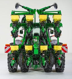
Folding markersA 406-mm (16-in.) notched marker disk blade with a 102-mm (4-in.) wide depth gauging band is base equipment on folding markers. Notched marker disk blades are compatible with all tillage conditions but are recommended for no-till and high-residue mulch-till conditions. This marker uses a 44.45-mm (1.75-in.) square tube marker arm extension. Folding markers are base equipment on the following planter model configurations:
Although not in base equipment, folding markers are available for the following integral planter configurations:
|
Vacuum systemVACUUM BLOWER ASSEMBLY
Vacuum is created by a hydraulically driven vacuum blower assembly mounted on the planter frame. The vacuum blower requires a tractor with a closed-center hydraulic system and a separate selective control valve (SCV). For tractors with open-center hydraulic system, a vacuum 540- or 1000-rpm power take-off (PTO)-driven hydraulic pump system is available. PTO pumps offered from the factory are limited to 15-row applications or less. Different vacuum levels are required depending on the crop being planted. A hydraulic control valve lets the operator regulate vacuum blower speed, changing the vacuum level. On late-model John Deere tractors, vacuum levels are set from the tractor seat using the SCV controls. The control valve is not needed in those applications. At full flow, the system flows up to 18.9 L/min (5 gpm) per motor. Convenient vacuum gauges located on the planter hitch give a visual indication of the vacuum level. When using a SeedStar™ monitor, the vacuum level can be displayed on the monitor. Consult the vacuum metering seed charts in the operator's manual for initial vacuum setting recommendations. VACUUM METER CASE DRAIN Vacuum is created by a hydraulically driven vacuum blower assembly mounted on the planter frame. The vacuum blower requires a tractor with a closed-center hydraulic system and a separate selective control valve (SCV). For tractors with open-center hydraulic system, a vacuum 540- or 1000-rpm power take-off (PTO)-driven hydraulic pump system is available. PTO pumps offered from the factory are limited to 15-row applications or less. Different vacuum levels are required depending on the crop being planted. A hydraulic control valve lets the operator regulate vacuum blower speed, changing the vacuum level. On late-model John Deere tractors, vacuum levels are set from the tractor seat using the SCV controls. The control valve is not needed in those applications. At full flow, the system flows up to 18.9 L/min (5 gpm) per motor. Convenient vacuum gauges located on the planter hitch give a visual indication of the vacuum level. When using a SeedStar™ monitor, the vacuum level can be displayed on the monitor. Consult the vacuum metering seed charts in the operator's manual for initial vacuum setting recommendations. VACUUM METER CASE DRAIN All planters with vacuum metering systems have case drain motors on the vacuum blowers. Case drain lines will have a flush-face case drain coupler on the planter and will require a corresponding flush-face case drain coupler on the tractor. The flush-face coupler simplifies implement attachment by allowing operators to easily identify the case drain. The unique hose tip is unable to connect to another coupler on the tractor, ensuring the correct setup. It is important to connect this case drain hose to prevent the continuous and complete draining of hydraulic fluid due to the relief feature that opens the coupler when the pressure reaches 10 psi. This relief feature is designed to protect the motor shaft seal if for any reason the case drain hose was not connected to the tractor. The flush-face hose tips have less back pressure than ISO case drain tips, and the flat surface makes these couplers easy to clean, providing less chance for contamination. The case drain line is also used with all Central Commodity System (CCS™) fan motors. |
Pneumatic downforce systemPneumatic downforce provides convenient, simple adjustment of downforce for the whole planter from one location. The amount of downforce applied is infinitely adjustable from 0 kg to 181.80 kg (0 lb to 400 lb). Pneumatic downforce provides more consistent downforce throughout the range of row-unit travel than mechanical spring downforce systems.
Such improvements to the pneumatic downforce system enable faster and more precise control of row-unit downforce while planting. SYSTEM FEATURES Each row-unit has a single, rubber air bag located between the parallel arms. The air bags are hooked in parallel so that air can be added or released from all rows at once from one location. An improved compressor is used to charge the pneumatic system. This compressor can be located on the planter frame or in the tractor cab if desired. A gauge at the compressor indicates the amount of downforce being applied. From the factory, integral planter models with pneumatic downforce will have an improved air compressor assembly with an in-cab mounting bracket, except the 1725 16-row and 1725 Central Commodity System (CCS™ ) Twin-Row Planters will have the air compressor assembly mounted on the planter frame. For drawn planter models, the 1755, 1765, 1765NT, 1775 Front-Fold, and 1785 Drawn Planters will have the air compressor assembly installed either on the outer hitch or wing frame members when the pneumatic downforce system is installed. |
Row cleaner options to meet residue management needsCrop yields have increased through the years along with the amount of residue left in the field after harvest. At the same time, tillage practices have changed, including different tillage operations which maintain large amounts of surface residue, and even no till practices. Row cleaners are an essential tool in managing this increased amount of residue. John Deere seeding group offers a variety of row cleaner options to meet the needs of a producer's operation. Compatibility varies by model, row spacing, and other planter equipment. SCREW-ADJUST UNIT-MOUNTED ROW CLEANER The screw-adjust unit-mounted row cleaner is mounted directly to the face plate of the row-unit, placing the ground engaging components just in front of the row-unit opener blades and depth gauge wheels. This close proximity allows the gauge wheels to control the depth of the row cleaner as well as the row-unit. This compact design also allows greater compatibility with fertilizer openers and other planter attachments. SharkTooth® wheels are standard equipment on the unit-mounted row cleaner. The swept-tooth design of the wheel provides a clear path for the row-unit openers while resisting residue buildup on the wheel. The screw adjustment knob is accessible through the top of the parallel arms, providing convenient access for adjustments. The row cleaner can be adjusted in 1.6-mm (0.06-in.) increments, providing plenty of flexibility to meet the needs of changing conditions. FLOATING ROW CLEANER WITH UNIT-MOUNTED COULTER The floating row cleaner allows a row cleaner to be used in conjunction with a unit-mounted coulter. This combination is often desired in heavy residue loads and tough reduced tillage planting conditions. The row cleaner provides a clear path for the row-unit, while the unit-mounted coulter helps penetrate tough soil conditions. Accommodating the unit-mounted coulter means the residue wheels are farther forward from the row-unit face plate than in the case of the screw adjust row cleaner. To maintain performance, this row cleaner has the capability to float above a defined minimum depth. Standard depth-gauging bands on the wheels allow the row cleaner wheels to float independently of the row unit openers, allowing both to perform in varying terrain. The unit may also be set in a fixed position by simply pinning through the bracket if desired. This row cleaner also features SharkTooth wheels as standard equipment. The floating row cleaner and unit-mounted coulters are available on many planters as factory-installed equipment. As compatibility and details vary by model, review the following links for information on specific planter models.
SharkTooth is a trademark of Yetter Manufacturing. NOTE: Screw-adjust row cleaners are not compatible with MaxEmerge™ 5e row-units with long parallel arms. NOTE: DB models have the option for either unit-mounted coulter, screw-adjust row cleaners, or pneumatic row cleaners (only compatabile with MaxEmerge 5e or equipped ExactEmerge™ models). The DB60T is only available with less row cleaner option. |
SeedStar™ 2 monitoring systemIntegrated innovation--that is what operators will appreciate with the SeedStar 2 monitoring system and GreenStar™ 2 (GS2) Display. An increasing number of acres combined with rising seed costs drive the need to easily understand planter functions and monitor performance. It is all about making every seed count and that is what SeedStar 2 delivers. The SeedStar 2 monitoring system is a full-feature, color, seed population monitor used in conjunction with the GreenStar family of displays (Generation 4 CommandCenter™ controls with premium activation, GS 2630, GS 2600 Display or the entry-level GS2 1800 Display). Conveniently, SeedStar 2 planting functions are fully integrated with the full spectrum of AMS applications—guidance, coverage maps, and field documentation can be shown all on one display. When a SeedStar 2 system is used on a planter, there is no need for a ComputerTrak™ monitor. All vital planting information is displayed in one central, easy-to-read location. SEEDSTAR 2 FEATURES SeedStar 2 is a user-friendly system that has retained all the valued features of SeedStar and incorporated the next generation of enhancements. For example, on-screen, color indicators shows drive engagement/disengagement status. In addition, three color (black, orange, or red) planter at a glance bars visually inform the operator of row population status. Not only does SeedStar 2 incorporate the use of color, it also utilizes an intuitive icon and folder based operator interface. Icons are easy to understand across many languages and reduce the need for text. Icons for planter main run page, planter setup, seed/crop setup, totals, and diagnostics are located in the soft-key region of the display. Setup is performed by selecting the appropriate icon and then choosing the tabs to enter/select information. The SeedStar 2 monitor offers all of the features and functionality of the ComputerTrak™ 350 monitor and much more. SeedStar 2 monitors the following planter functions:
In addition, planter operational information is available within the SeedStar 2 monitor system. Such operational information includes population charts, seed disk vacuum settings, and setting recommendations for the piston pump liquid fertilizer system. All SeedStar 2 systems have the capability, through a single controller, to perform both the seed monitoring and variable rate drive functions. SeedStar 2 monitoring is required for VRD population control. Even though the planter may not be equipped with SeedStar 2 VRD, the SeedStar 2 monitoring system is available and will allow for future installation of VRD. SEEDSTAR 2 ENHANCEMENTS The SeedStar 2 enhanced planter features include:
SEEDSTAR MONITORING ORIGINAL FEATURESSeedStar 2 retains all those SeedStar features that producers value and have come to expect:
|
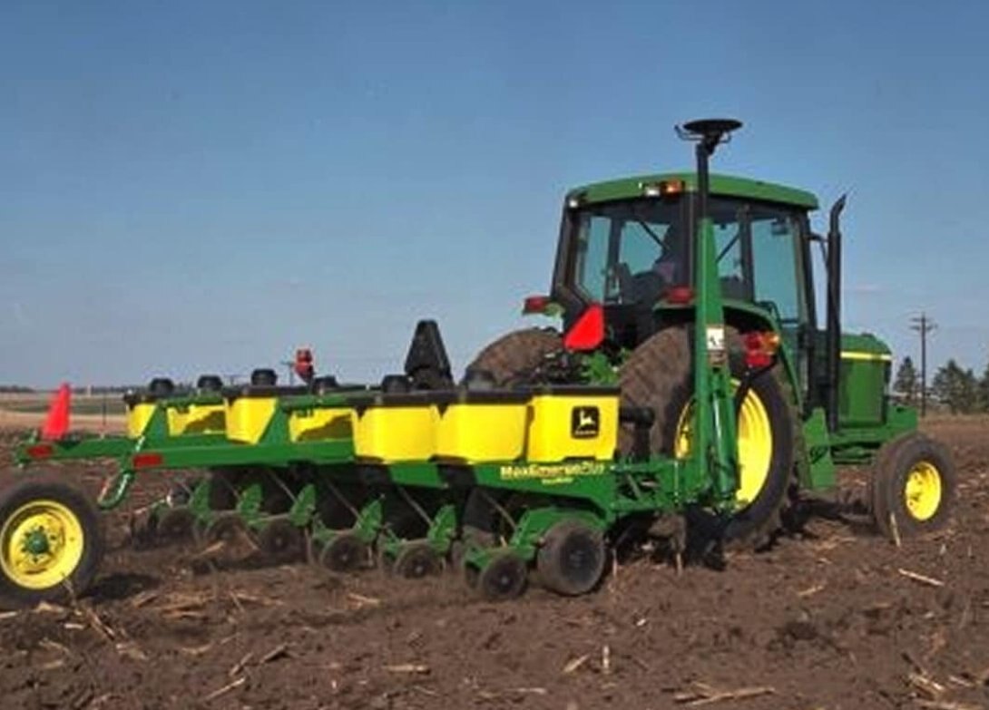
Ground-contact drive wheelThe ground-engaging drive wheel system is a simple, proven, and reliable way to power the seed transmission(s). As the drive wheel turns, power is transmitted through a single-pitch drive chain to the jack shaft, on to the seed transmission, and out to the seed meters. Slip-clutch protected, spring-loaded idlers and steel sprockets provide a smooth-operating, dependable chain drive. The ground-contact drive system has the following common features:
1705, 1715, AND 1725 PLANTERS 1705, 1715, and 1725 Planters (except 1725 16Row30) are driven from one rear-mounted, ground-contact wheel. 1735 PLANTER DRIVE A 1735 Planter is driven by one, front-mounted, ground-contact wheel. 1755 PLANTER DRIVE Using ground-contact drive wheels much like the integral planters, the 1755 Drawn Planter utilizes two drive wheels. |
Seed variable-rate driveSeed variable-rate drive provides the ultimate planting productivity by utilizing one, two, or three hydraulic motors (varies by model) to turn the seeding drive shaft. Hydraulic control of the seeding drive allows for on-the-go seeding rate changes right from the display mounted inside the tractor cab. Combine this seeding flexibility with the map-based planting option, and seeding rates adjust automatically based on the prescribed map. Variable-rate drive offers the following advantages over common, ground, or contact-tire drive systems:
Single- or dual-motor systems for variable-rate drives are available for all John Deere planters except the 1785 Rigid Frame. Variable-rate drive is available as a factory-installed option for all applicable planter models. NOTE: Peanut seed meter disks require the Variable Drive Transmission. |
Battle River Implements Ltd.
Phone: 1.877.913.3373
Monday - Friday:
7:30 AM - 5:30 PM
Saturday:
8:00 AM - 4:00 PM
Sunday:
Closed