
My Cart - items
items in your cart
Order summary
Total:
Grand Total:
*Shipping & taxes calculated at checkout

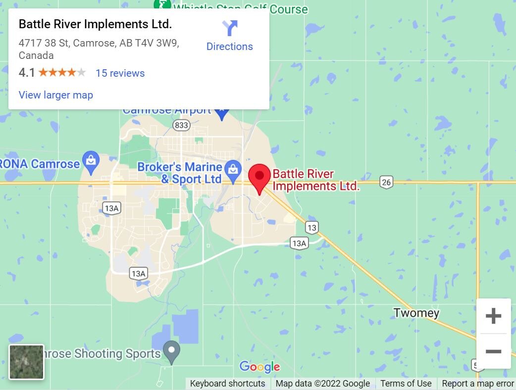
Pneumatic downforce system
|
Vacuum systemVACUUM BLOWER ASSEMBLY Vacuum is created by a hydraulically driven vacuum blower assembly mounted on the planter frame. The vacuum blower requires a tractor with a closed-center hydraulic system and a separate selective control valve (SCV). For tractors with open-center hydraulic system, a vacuum 540- or 1000-rpm power take-off (PTO)-driven hydraulic pump system is available. PTO pumps offered from the factory are limited to 15-row applications or less. Different vacuum levels are required depending on the crop being planted. A hydraulic control valve lets the operator regulate vacuum blower speed, changing the vacuum level. On late-model John Deere tractors, vacuum levels are set from the tractor seat using the SCV controls. The control valve is not needed in those applications. At full flow, the system flows up to 18.9 L/min (5 gpm) per motor. Convenient vacuum gauges located on the planter hitch give a visual indication of the vacuum level. When using a SeedStar™ monitor, the vacuum level can be displayed on the monitor. Consult the vacuum metering seed charts in the operator's manual for initial vacuum setting recommendations. VACUUM METER CASE DRAIN Vacuum is created by a hydraulically driven vacuum blower assembly mounted on the planter frame. The vacuum blower requires a tractor with a closed-center hydraulic system and a separate selective control valve (SCV). For tractors with open-center hydraulic system, a vacuum 540- or 1000-rpm power take-off (PTO)-driven hydraulic pump system is available. PTO pumps offered from the factory are limited to 15-row applications or less. Different vacuum levels are required depending on the crop being planted. A hydraulic control valve lets the operator regulate vacuum blower speed, changing the vacuum level. On late-model John Deere tractors, vacuum levels are set from the tractor seat using the SCV controls. The control valve is not needed in those applications. At full flow, the system flows up to 18.9 L/min (5 gpm) per motor. Convenient vacuum gauges located on the planter hitch give a visual indication of the vacuum level. When using a SeedStar™ monitor, the vacuum level can be displayed on the monitor. Consult the vacuum metering seed charts in the operator's manual for initial vacuum setting recommendations. VACUUM METER CASE DRAIN All planters with vacuum metering systems have case drain motors on the vacuum blowers. Case drain lines will have a flush-face case drain coupler on the planter and will require a corresponding flush-face case drain coupler on the tractor. The flush-face coupler simplifies implement attachment by allowing operators to easily identify the case drain. The unique hose tip is unable to connect to another coupler on the tractor, ensuring the correct setup. It is important to connect this case drain hose to prevent the continuous and complete draining of hydraulic fluid due to the relief feature that opens the coupler when the pressure reaches 10 psi. This relief feature is designed to protect the motor shaft seal if for any reason the case drain hose was not connected to the tractor. The flush-face hose tips have less back pressure than ISO case drain tips, and the flat surface makes these couplers easy to clean, providing less chance for contamination. The case drain line is also used with all Central Commodity System (CCS™) fan motors. |
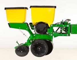
Advance with MaxEmerge™ 5 advantages
|
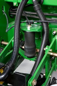
Ground-contact drive wheelThe ground-engaging drive wheel system is a simple, proven, and reliable way to power the seed transmission(s). As the drive wheel turns, power is transmitted through a single-pitch drive chain to the jack shaft, on to the seed transmission, and out to the seed meters. Slip-clutch protected, spring-loaded idlers and steel sprockets provide a smooth-operating, dependable chain drive. The ground-contact drive system has the following common features:
1705, 1715, AND 1725 PLANTERS 1705, 1715, and 1725 Planters (except 1725 16Row30) are driven from one rear-mounted, ground-contact wheel. 1735 PLANTER DRIVE A 1735 Planter is driven by one front-mounted ground-contact wheel. 1755 PLANTER DRIVE Using ground-contact drive wheels much like the integral planters, the 1755 Drawn Planter utilizes two drive wheels. |
John Deere Connected Support™ prevents downtime and efficiently resolves issues with revolutionary technology-based solutions
|
Seed variable-rate drive provides the ultimate planting productivitySeed variable-rate drive provides the ultimate planting productivity by utilizing one, two, or three hydraulic motors (varies by model) to turn the seeding drive shaft. Hydraulic control of the seeding drive allows for on-the-go seeding rate changes right from the display mounted inside the tractor cab. Combine this seeding flexibility with the map-based planting option, and seeding rates adjust automatically based on the prescribed map. Variable-rate drive offers the following advantages over common, ground, or contact-tire drive systems:
Single- or dual-motor systems for variable-rate drives are available for all John Deere planters except the 1785 Rigid Frame. Variable-rate drive is available as a factory-installed option for all applicable planter models. NOTE: Peanut seed meter disks require the variable-drive transmission. |
Battle River Implements Ltd.
Phone: 1.877.913.3373
Monday - Friday:
7:30 AM - 5:30 PM
Saturday:
8:00 AM - 4:00 PM
Sunday:
Closed